When there is a torsion moment in a concrete beam, XFEM4U does some calculations based on longitudinal reinforcement and stirrup configuration. It then states the following:
There is an amount of additional longitudinal reinforcement required.
When increasing the amount of longitudinal reinforcement from, say, 2xø16 to 4ø16, the required amount doesn’t change.
When adding reinforcement inside a second layer (offset to be flank reinforcement), the amount decreases, but not by the amount of reinforcement added.
Torsional moments should be dealt with with stirrups and flank reinforcement (is that the correct English term?), but it appears this is not possible. Would it be possible to add flank reinforcement?
In the attached PDF/xfem, there are 4 identical beams with identical loads. Their reinforcement is altered to see the influence of longitudinal reinforcement.
Beam 1: 2ø12 / 2ø16; Asl,req = 223 (I considered this my base)
Beam 2: 4ø12 / 4ø16; Asl,req = 223 (extra longit.reinf. but the same result)
Beam 3: 2ø12+2ø8 / 2ø16 + 2ø8; Asl,req = 165 (extra longit.reinf. in 2nd layers with different result)
Beam 4: 4ø12 / 4ø16 + stirrups 4s; Asl,req = 223 (extra stirrup legs, but the same result)
It’s easy enough to manually calculate that 223 mm2 is 4ø10, spreaded along the perimiter. However, the warning message doesn’t stand out from the rest of the text. Maybe this could be highlighted or marked bold?
First of all. You are able to get a detailed concrete calculation in any section. How? Go to tab Concrete and click on the menu button Concrete cross section. Click in the side view of beam to determine the place. In the dialog Concrete cross section in detail you are now able to get the detailed calculation.
Using this I have made two detailed calculations of beam 1 and beam 3. beam1.pdf (146.8 KB) beam3.pdf (149.7 KB)
In both cases the extra required longitudinal reinforcement due to torsion is Asl=223 mm2. Why the output you’ve send (torsion.pdf) shows otherwise for beam 3 Asl=165 mm2 I do not know yet. We will have to examine this further. Your helpdesk number is #1982.
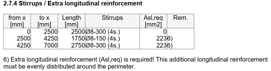
Note that stirrups will be designed on the combination of shear and torsion. If torsion reinforcement is required it consists of stirrups (that is dealt with already) and extra longitudinal reinforcement divided along the 4 sides. This extra reinforcement has to be added manually.
Thank you for looking into it. I hadn’t compared the calculations with the output, strange to see it’s different.
Is there any chance to see the message about additional required longitudinal reinforcement stand out more? Or maybe even add an extra chapter at the end with a short summary, where this is mentioned again per beam? It is quite easy to overlook in its current setup.
Yes. We will improve the output of additional required longitudinal reinforcement. I fully agree. Now it is quite easy to overlook this. And this reinforcement is essential.
We could print this in bold in Green. Your suggestion to add an extra table with overview of this reinforcement is a good idea also. Your helpdesk number is #1982.